Más
Packaging technology
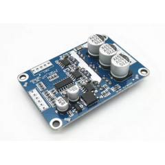
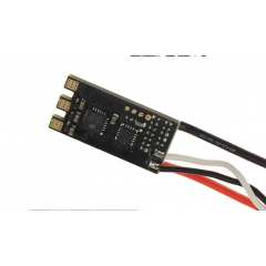
DFN packaging technology BLDC wide voltage 12-30V high power 200W DC three-phase brushless Hall controller, support PLC 0-5V simulation control support PWM to 0-5V control, only suitable for the electrical Angle of 1 20 degrees DC brushless Hall motor.
Product parameters
Product name: 200W brushless Hall DC motor driver
Model: XY-BLDC
Operating voltage: 12-30V
High current: rated 7A, peak 10A
High power: 200W
Overcurrent protection: Yes
Forward and reverse: Yes
Brakes: Yes
Speed regulation PWM: Yes
Speed control simulation quantity: Yes
Product size: length 80MM*width 3OMM*height 10MM
Weight: 14.68
Input instructions
Instruction of external signal:
1. When the external PWM signal is input, the amplitude is 5V, and the recomm
ended frequency of PWM is 1K-10KHz.
2. When the analog input, you can use the board 5V, GND external potentiomete
r (resistance value 10K-100K02) for speed regulation, can also be external inpu
t (0-5V) analog quantity, but it needs to be connected with GND on the board.
3. In the control of positive and negative rotation, it is necessary to carry out p
ositive and negative rotation after the motor stops rotating. It is strictly prohibi
ted to change direction during the motor rotation, which will cause damage to t
he circuit board. In addition, after the short circuit cap is removed, the external
steering switch can be connected for operation.
4. 5V, GND motherboard comes with 5V power supply (external power supply, th
e current does not exceed 10mA)
5. Speed pulse signal output, the amplitude is 5V, each pulse represents the mot
or rotation one circle.
Matters needing attention
1. There is no fuse on the power supply circuit of the motherboard, and ¡t is ad
ded by ¡tself. The positive and negative connection of the power supply will ca
Use permanent damage to some chips on the board.
2. There is sampling overcurrent protection at the output end of the motor durin
g normal operation. As the power and current of the module are very large, plea
se do not short-circuit artificially when the module is not working normally. Be
cause ¡it is a bare board module for sale, note that the insulation of wiring head
is strictly forbidden to encounter strong voltage on the board parts.
3. When the power of the drive module is more than 100W or the environment ¡
s more than 30"C, external air cooling shall be provided for the circuit board fo
r heat dissipation in order to ensure the long-term normal operation of the circu
it board.
4, Receive the goods, ¡f there is no clear connection and use, please contact us
for the first time to communicate, even ¡f there is a problem in the use of the p
roduct, you can also negotiate properly handled.
Debug instructions
Please see and understand after the power test machine, very important very imp
ortant very important!!
After receiving the drive board, first understand whether the interface can corres
pond to the interface of your brushless motor.
1. Brushless motor in general there are 5 hall row thread or interface, of which
two are three root is hall hall supply lines. signal lines. power line to distinguis
h especially hal! (hall of power supply line with red and black commonly, also h
ave no, don't know to find a way to find motor manufacturers to) don't make a m
istake, three hall signal lines generally marked a b c, There are three similar cha
racters on the drive board, such as HA, HB and HC, which should be connected
well respectively
2. There are three thick phase lines on the motor and three phase lines on the dr
ive board. They are marked with similar characters such as MA, MB, MC, etc. Th
ey should also be connected respectively. (If the interface is correctly matched a
ccording to the mark, the power can not work normally, nor does ¡t exclude the p
ossibility that the manufacturer's mark is not standard or other reasons. please fo
llow the following unclear to debug)
* If the definition of motor phase line and Hall line is not clear, the three phas
e lines of the motor can be arbitrarily connected to the interface of the drive ph
ase line, and at the same time, the three signal lines of Hall line can be arbitrar
ily connected to the interface of Hall line on the drive board (but the two Hall
power lines must be found out and matched, remember!!). Then, during the first
power-on, low voltage and low current debugging (if possible, adjust the voltag
e of the constant current power supply to 7-12V current 1-2A), and then exchan
ge the order of the three Hall wires arbitrarily (exchange any two Hall signal lin
es between the three Hall signal lines of the motor and the driving Hall interfac
e, and test the power-on once each switch). Until the power can be smooth rotat
ion of the operation after the wiring is correct.
* When the wiring is not correct, do not debug with large current and high volta
ge, otherwise there will be a risk of damage to the drive plate. If the three Hall
signal lines are replaced, they will be connected correctly, and the motor will st
art smoothly and smoothly at low speed after energizing, like smooth running wi
re. If the sequence of the three Hall signal lines is not matched, they generally h
ave the following characteristics:
1. After energizing, the motor cannot start normally without reaction or it can o
nly shake once when starting and cannot rotate normally
2. It is difficult to start with slight jitter, and sometimes it needs to be turned m
anual ly
3. The motor can turn in one direction, but not in the other direction, and some
of them have slight bath sound
4. The motor starts with great jitter and weakness, and the large power tube wit
h bath sound and current is obviously heated seriously.
7 productos más en la misma categoría:
-

Mejor Precio Garantizado
En nuestra tienda encontrará los mejores precios.
-

Soporte
Por cualquier duda, puede comunicarse con nosotros.
-

Ofertas
Acceda a las mejores ofertas en nuestros productos.