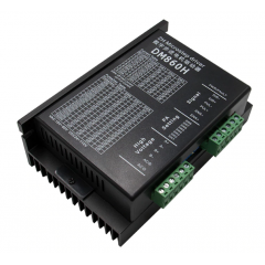
Stepper Driver 4a Microstep Motor Paso 9-40v Tb6600 Pro Itytarg
MLA896568300
Nuevo producto
Peso: 155g
Type: HJG-093
La versión PRO solo varía en el tamaño del disipador de calor
Este producto ya no está disponible
Más
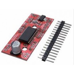
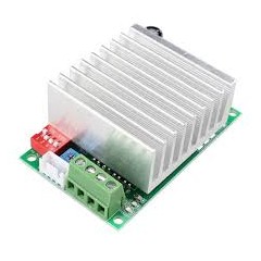
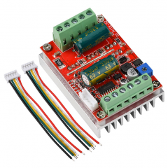
Este driver de referencia TB6600 4.0A basado en el chip TB6600 es un módulo controlador de motor paso a paso de tipo bipolar que permite varios modos micro-paso. Compatible con motores de 2 y 4 fases de 12V a 40V de tensión, la corriente de excitación máxima es de menos de 5 A.
Esta unidad utiliza el control de la subdivisión del bucle de corriente, el rizado del par de torque del motor es muy pequeño, baja velocidad de funcionamiento muy suave. El torque de alta velocidad es mucho mayor que otras unidades de dos fases, de alta precisión de posicionamiento. Ampliamente utilizado en las máquinas de grabado, máquinas CNC, maquinaria de embalaje y otros equipos. Motores NEMA17, NEMA23, NEMA24 y NEMA34 funcionan a la perfección con este controlador.
TAMAÑO DEL DISIPADOR: 95X35mm
Características
- Modo seleccionable de micro paso (1/1, 1/2, 1/4, 1/8, 1/16 1/32 paso).
- Fuente de alimentación sencilla.
- Control de corriente (en 8 pasos de 0,2 A a 4 A).
- Fuente de alimentación: 12 ~ 40V DC
- Entradas aisladas ópticamente
- Protección contra sobre voltaje, bajo voltaje, sobrecorriente y cortocircuitos.
- Alta velocidad de partida.
- Torque de alta velocidad.
- Carcasa de plástico negro resistente y disipador de calor de aluminio negro.
- Orificios de montaje sobre el disipador de calor para el montaje de la unidad en paneles de la máquina.
Especificaciones técnicas
- Voltaje de entrada DC: 8 ~ 40V (Voltaje operativo: 12V – 42V)
- Corriente de entrada de 1 a 4 A
- Corriente de salida:
- IOUT= 4.0 A (Valor nominal máximo absolutos, pico, de 100 ms)
- IOUT= 3.5 A (rango de operación, valor máximo)
- Temperatura de funcionamiento: -10 to 45 ℃
- Temperatura de almacenamiento: -40 ℃ to 70 ℃
- Peso: 200 gramos
Introduction
This is a professional two-phase stepper motor driver. It supports speed and direction
control. You can set its micro step and output current with 6 DIP switch. There are 7 kinds
of micro steps (1, 2 / A, 2 / B, 4, 8, 16, 32) and 8 kinds of current control (0.5A, 1A, 1.5A, 2A, 2.5A, 2.8A, 3.0A, 3.5A) in all. And all signal terminals adopt high-speed optocoupler
isolation, enhancing its anti-high-frequency interference ability. Features:
Support 8 kinds of current control
Support 7 kinds of micro steps adjustable
The interfaces adopt high-speed optocoupler isolation
Automatic semi-flow to reduce heat
Large area heat sink
Anti-high-frequency interference ability
Input anti-reverse protection
Overheat, over current and short circuit protection
INPUT & OUTPUT:
Signal Input:
PUL+ Pulse +
PUL- Pulse - DIR+ Direction +
DIR- Direction - EN+ Off-line Control Enable +
EN- Off-line Control Enable - l Motor Machine Winding:
A+ Stepper motor A+
A- Stepper motor A- B+ Stepper motor B+
B- Stepper motor B- l Power Supply:
VCC VCC (DC9-42V)
GND GND
l Wiring instructions
There are three input signals in all:
1) Step pulse signal: PUL +, PUL-;
2)Direction: signal DIR +, DIR-
3) off-line signal: EN +, EN-.
The driver supports common-cathode and common-anode circuit, you can select one according to your demand.
Common-Anode Connection:
Connect PUL +, DIR + and EN + to the power supply of the control system.
If the power supply is + 5V, it can be directly connected. If the power supply is more than +5V, the current limiting resistor R must be added externally.
To ensure that the controller pin can output 8 ~ 15mA current to drive the internal optocoupler chip.
Pulse signal connects to PUL-; direction signal connects to Dir- ; Enable signal connects to EN-. As shown below:
Common-Cathode Connection:
Connect PUL -, DIR - and EN - to the ground terminal of the control system.
Pulse signal connects to PUL-; direction signal connects to Dir- ; Enable signal connects to EN-.
30 productos más en la misma categoría:
-
Drv8825 Pololu Stepper Driver...
-
Stepper Driver 15v Max 1.2a...
-
A3967 Easydriver Stepper Driver...
-
Modulo A4988 Pololu Driver Motor...
-
Stepper Driver Tb6600 V1.2...
-
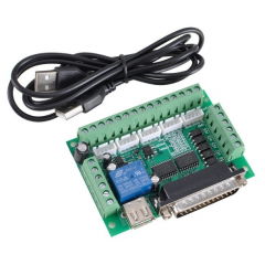
5 Axis Cnc Inteface Board Lpt...
-
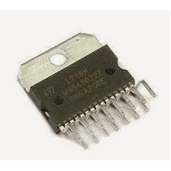
L298 N L298n Stepper Driver...
-
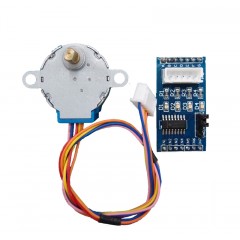
Motor 28byj-48 Stepper Driver...
-

Doble Stepper Driver Vnh2sp30...
-
Stepper Driver Bipolar Big Easy...
-
A3967 Dual 2ch Stepper Driver...
-
Tb6612 Shield Arduino Uno I2c...
-
Breakout Hc3dpr0038 Expansion...
-
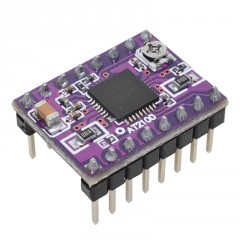
At2100 Stepstick Stepper Motor...
-
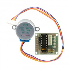
Kit Motor Stepper Con Reduccion...
-
Dm860h Stepper Driver Alta...
-
A4988 V1.2 Pololu Driver Motor...
-
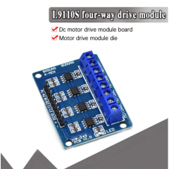
L9110s 4ch Dc Motor Driver...
-
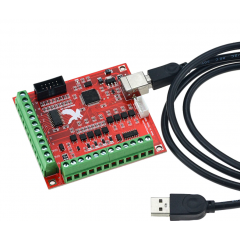
4 Axis Cnc Inteface Board Usb...
-
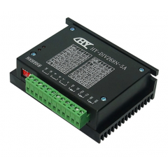
Hy-div268n-5a Stepper Driver...
-
L6470 Stepper Driver 3a, 8-45v...
-
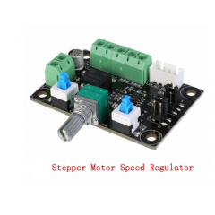
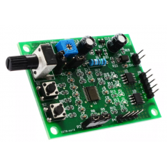
Control Velocidad Para Stepper...
-
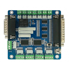
5 Axis Cnc Inteface Board Lpt...
-
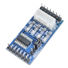
Uln2003 Stepper Motor Driver...
-
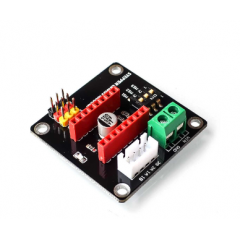
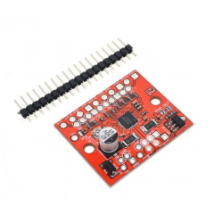
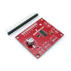
Breakout Expansion Stepper Motor...
-
Stepper Driver Multifuncion...
-
Stepper Driver Brushless Zs-x11h...
-
L298n Generico Stepper Driver...
-
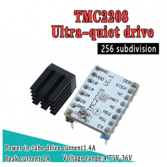
Tmc2208 Driver Motor Paso A Paso...
-
Dm556 Stepper Driver 20v A 50v...
-

Mejor Precio Garantizado
En nuestra tienda encontrará los mejores precios.
-

Soporte
Por cualquier duda, puede comunicarse con nosotros.
-

Ofertas
Acceda a las mejores ofertas en nuestros productos.