Más
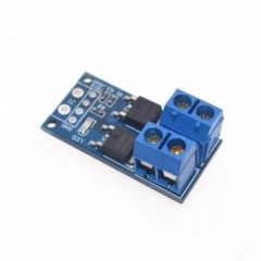
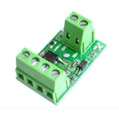
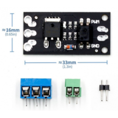
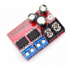
IRF520 Mosfet Driver Module
This IRF520 Mosfet Driver module is easy to hookup to your Arduino or the other 3-5V microcontroller. The module designed to switch heavy DC loads from a single digital pin of your microcontroller. Its main purpose is to provide a low cost way to drive a DC motor for robotics applications, but the module can be used to control most high current DC loads. Screw terminals are provided to interface to your load and external power source.
Specification:
- Voltage: 3.3V, 5V
- Output load voltage :0-24V
- Output load current: <5A (1A need to add more heat sink)
- Platform: Arduino, MCU, ARM, Raspberry Pi
- Using original IRF520 Power MOS, you can adjust the output PWM.
- Drive up to 24V allows the load, such as LED lights, DC motors, miniature pumps, solenoid valves.
- PWM dimming LED can be used to achieve step less dimming, variable speed motor control.
Note: Above 1A load, you need to install heat sink
DESCRIPTION
The IRF520 N-Ch MOSFET Module can control loads up to 24V @ 5A.
PACKAGE INCLUDES:
- IRF520 N-Ch MOSFET Module
KEY FEATURES OF IRF520 N-CH MOSFET MODULE:
- Switch loads up to 24V @ 5A
- 5V compatible (actually semi-compatible. See notes below)
The IRF520 is not fully 5V logic compatible but it will work fine for many applications if it is derated to the specs we show here. See our evaluation results down below for more detail on that aspect of the module.
These modules can be used to control motors, fans, LEDs and other devices.
Module Connections
The connectors can look a bit confusing at first, but hook-up is fairly straight forward. The attached schematic can help clarify things.
To hook-up:
- Connect the load to be controlled across the V+ and V- terminals observing the correct polarity.
- Connect the power supply (up to 24V) across the Vin and GND terminals.
- Connect the uC ground and control pin to the GND and SIG header pins on the module. The center pin on the header marked ‘VCC’ is not connected.
The ‘SIG’ control input is active HIGH and 5V compatible, but can be driven as high as 10V to drive the IRF520 into full saturation. There is a green LED that lights when SIG is active HIGH
A 1K pull-down resistor is included on the module to help to ensure that the transistor will be in the off state when the microcontroller is powering up and the outputs are floating.
1 x 3 Male Header
- SIG = Signal input (active HIGH). Typically used with 5V logic. Can be driven at up to 10V to fully turn on the IRF520.
- VCC = No connection
- GND = Digital ground.
1 x 2 Screw Terminal (Load)
- V+ = Connect to positive lead of load (motor, LEDs, fan, etc)
- V- = Connect to negative lead of load
1 x 2 Screw Terminal (Power)
- VIN = Connect to power supply (0-24V) being used to power the load
- GND = Connect to power supply ground
OUR EVALUATION RESULTS:
The IRF520 MOSFET device is actually rated for up to 100V @ 9.7A. That rating assumes that it is being driven by a gate voltage of 10V to fully turn the device on with good heat sinking, etc.
Since this module is mainly designed to be used with an Arduino or similar uC that can only drive 5V, the IRF520 will not be driven to full saturation and therefore will dissipate more heat. For that reason it needs to be derated from the theoretical maximum specs which is how we end up with our 24V @ 5A rating.
In our load testing, driving it with a 5V logic signal and pulling 3A continuous resulted in 56C on the tab and 3.5A resulted in 71C which is about as high as I would drive it unless a heat sink is added. If the transistor is being quickly switched such as when using PWM, pulling 5A is possible without a heat sink. At a 50/50 duty cycle with 5A we measured 75C. These measurements were all made with no heatsink.
I don’t recommend using this module with 3.3V logic since the thermal performance will be worse, but if you do, limit the current to about 1A to be on the safe side.
Notes:
- None
TECHNICAL SPECIFICATIONS
| Maximum Ratings | IRF520 Device Specs | |
| VDSS | Drain-Source Voltage | 100V (24V in this application) |
| ID | Drain Current | 9.7A (5A in this application) |
| RDS | Drain-Source On-Resistance | 0.25Ω (at 10V gate) |
| PD | Power Dissipation | 48W (requires heat sink) |
| Package | TO-220 | |
| Package Type | Plastic Tab, 3-lead, through hole | |
| Mfr | International Rectifier | |
| Datasheet |
27 productos más en la misma categoría:
-
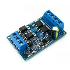
Mosfet Motor Driver Pwm 15a 400w...
-
Driver Mosfet Chn Irf540 100v...
-
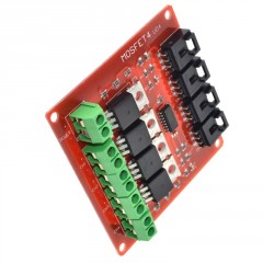
Interfaz 4ch Mosfet Chn Irf540...
-
Driver Mosfet 1ch Irf5305s 55v...
-
Driver Mosfet 1ch Fqd60n03 30v...
-

Modulo Fr120n Mosfet Optoacopldo...
-
Modulo Aod4184 Mosfet...
-

Modulo Lr7843 Mosfet Driver...
-
Driver Mosfet 2ch 10a Control...
-
L298n Doble Puente H Driver...
-
Simple Motor Driver Vnh2sp30...
-
L298 Doble Puente H Driver L298n...
-
Cnc Shield V3 S/ A4988 Pololu...
-
L293d Mini 4ch Motor Driver Itytarg
-
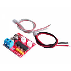
Interfaz Uln2003 Driver Motor...
-
Doble Puente H Driver L298 L298n...
-

Controlador Motor Driver Alta...
-
Vnh5019 1ch Simple Motor Driver...
-
Zk-5ad Puente H Driver Pwm Motor...
-
Xy160d Motor Driver 160w 7a Dual...
-
Mx1508 Minil298n Doble Puente H...
-
Driver Motor Dc Puente H 1.5a 3v...
-
Driver Motor Dc Puente H 1.5a 3v...
-
Hg7881 Motor Driver 4ch...
-
Modulo A4950 Dual Motor Driver...
-
Mx1919 Dual Driver Controlador...
-
Driver Dual Motor Dc 10a 3-18v...
-

Mejor Precio Garantizado
En nuestra tienda encontrará los mejores precios.
-

Soporte
Por cualquier duda, puede comunicarse con nosotros.
-

Ofertas
Acceda a las mejores ofertas en nuestros productos.