Ver más grande


Controlador Fat Ch376 Ch376s C/sd Memoria Usb Itytarg
13335
Nuevo producto
Cod: GAW
3 artículos
Advertencia: ¡Últimos artículos en stock!
Más
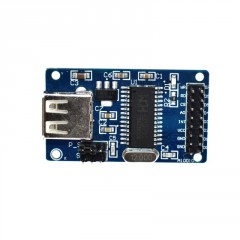
Product introduction
CH376 evaluation board contains CH376S chip and auxiliary components, excluding single chip microcomputer. It is reserved for 8-bit parallel port, SPI interface, asynchronous string and power port, etc., for connecting with other single chip microcomputer motherboards, and the motherboard of single chip microcomputer controls CH376 for function evaluation.
Pin definition
1. The main component U1 in the evaluation board is CH376S chip, but some si
gnals in the figure are named after CH375 or CH374.
2. Crystal *1 is standard 12MHz, USB host requires higher frequency accuracy th
an USB devices, the error of *1 ¡s less than 0.4%, ordinary 12MHz crystal can b
asically meet the requirements.Shortening the length of the relevant leads is stro
ngly recommended to reduce interference.
3. Capacitor C4 ¡is used for internal power supply node decoupling to reduce EM
| during USB transmission. The capacity is 4700pF to 0.1uF, and ordinary 103 p
atch capacitor 0.01uF can be used.
4. P4 ¡is a USB port, which can be used in both USB HOST mode and USB DEVI
CE mode. Resistor R1 is used to limit the current output to external USB device
s, so as to avoid short time drop of power supply voltage when USB devices suc
h as U disk are just inserted, or even cause abnormal reset of CH376 or SCM or
internal RAM data error.If it is a USB external hard disk, you should replace the
resistor R1 with an inductor with a smaller DC resistance, or use another 5V po
wer supply to directly provide a larger working current (more than 500mA) to th
e external hard disk.In addition, the capacity of the power decoupling capacitor
C9 of the USB-Host socket should not be too small. A larger capacity (should b
e greater than 100uF) can reduce the fluctuation of the power supply voltage wh
en the USB device is just plugged in.
5. P5 ¡is the SD card socket, which can contact the SD card of standard size, and
the SD card of other specifications may need an additional conversion seat.The
resistor R3 is used to limit the current output to the external SD card to avoid a
short drop in the supply voltage when the SD card ¡is just inserted.
6. P1 is the signal port of the 8-bit parallel port, which is used to connect the p
arallel port of the single chip microcomputer. The necessary signals of the paral
lel port include DO-D7, AO, RDH, WR+, CSH and GND, while INT+ is optional.
7. P2 is the signal port of the SPI serial port, which is used to connect the SPI
interface of the single chip microcomputer. The necessary signals of SPI includ
e SCS, SCK, SDL, SDO and GND, while INTHt is optional.
8. P3 is the signal port of the asynchronous serial port, which is used to connec
t the asynchronous serial port of the single chip microcomputer. The necessary s
ignals of the asynchronous serial port include RXD, TXD and GND, while INT+ ¡
s optional.P3 provides both write-protected SDWP and plug-and-state SDINSERT
signal lines for the SD card.
A The above P1, P2 and P3 communication ports can also provide 5V power su
pply to the evaluation board from the outside, as well as optional hardware rese
t signal to the RSTI pin of CH376. If there is a UP monitoring circuit in the act
ual product circuit, the same reset signal should be provided to CH376 and MC
U.Note that the length of the signal line between the evaluation board and the S
CM should be shortened as far as possible, the longest can not exceed 20cm, ot
herwise it is necessary to use a special circuit with a signal interval of one gro
und wire.J3 ¡s used to select the working voltage of CH376 chip, which is 5V
when shorting 1-2 pins and 3.3V when shorting 2-3 pins.The default voltage ¡is
5V, but when the working voltage of SCM is equal to or lower than 3.3V, 3.3V
voltage can be selected for CH376.When CH376 chip working voltage is 5V, J2
must be disconnected, when CH376 chip working voltage is 3.3V, J2 must be sh
ort-connected.
Directions for use
CH376 evaluation board description:
1, J5 and J6 are used to select the communication connection between CH376
and SCM after power on or hardware reset:
If J1 is short, J5 is disconnected, J6 is disconnected, then it is 8-bit parallel p
ort;
If J1 is disconnected, J5 is short, J6 ¡s short, then it is SPI interface;
If J1 is disconnected, J5 is disconnected, or J6 is disconnected, it is an asynch
ronous serial port.
+ Some examples of programs may use the single-chip serial port output debugg
ing status information, ¡f you need to display these monitoring information, you
can be connected to the computer after the single-chip string RS232 level conv
ersion using the serial port monitoring/debugging tool software to view.If you u
se CH375 evaluation board, you can connect J2 to a computer serial port;lf the
computer does not have a serial port, or the serial port has been occupied by ot
her devices, then you can provide simulation serial port from USB to serial chip
CH341.
+ The CH375 evaluation board must add the resistor RO and remove the 3.3V re
gulator D4 when operating at 5V supply voltage, and add the regulator D4 and r
emove the resistor Ro when operating at 3.3V supply voltage.The default is 5V
power.
2 productos más en la misma categoría:
-

Mejor Precio Garantizado
En nuestra tienda encontrará los mejores precios.
-

Soporte
Por cualquier duda, puede comunicarse con nosotros.
-

Ofertas
Acceda a las mejores ofertas en nuestros productos.