Ver más grande

¡Disponible sólo en Internet!
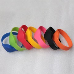
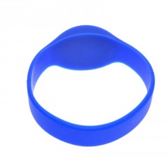
Pulsera Silicona Rfid 125khz Tk4100 Sumergible Celeste Itytarg
MLA854729774
Nuevo producto
416 artículos
Más
Tamaño mediano (medium) 70mm
Color Celeste
Código Fijo
Consúltenos y le proveeremos según su requerimiento
EM4100 Protocol description.
| RFID transponders (Tags) are devices carrying digital information that can be read from a distance by a RFID transceiver (Reader). In order to be able to read the information stored on the RFID tags the reader must know how the information is stored and the protocol for extracting it. One of the more common data formats for RFID transponders is the EM4100 protocol, named so because the microchip at the heart of the Tag is based on the controller chip made by the company EM Microelectronic. |
||||||||||||||||||||||||||||||||||||||||||||||||||||||||||||||||||||||||||||||||||||||||||||||||||||||||||||||||||||||||||||||||||||||||||||||||||||||||||||||||||||||||||||||||||||||||||||||||||||||||||||||||||||||||||||||||||||||||||||||||||||||||
Reading an EM4100 RFID Transponder.EM4100 compatible RFID transponders carry 64 bits of Read Only memory. This means that informationcan be read from the Tag but no data can be changed, or new data written to the card once the card has been programmed with the initial data. The format of the data is as shown here.
When the Tag enters the electromagnetic field transmitted by the RFID reader it draws power from the field and will commence transmitting its data as shown above. The first 9 bits are a logic 1. These bits are used as a marker sequence to indicate the beginning of the string. As Even parity is used throughout the data this 9 bit sequence of 1's will not occur at any other location in the string. This is followed by 10 groups of 4 data and 1 even parity bits. Finally there are 4 bits of column parity (Even) and a stop bit (0). The Tag then continues to repeat this string as long as it has power. Shown here is an example string for a proximity card that has the data $06 (version number), and $001259E3 as a data string.
Data modulation.As discussed in RFID basics the RFID transponder is able to transmit its data by modulating the RF field ofthe Reader. Here we discuss 3 popular modulation schemes. Manchester Encoding.
BiPhase Encoding. PSK Encoding. The Transponder and Reader use the individual cycles of the RF field to syncronize the data transmission between the two. The frequency of the synchronizing clock then simply becomes the frequency of the RF field used. RFID system clock frequencies vary according to the application required. In low frequency, short distance sensing of Tags the typical band used is between 100-150Khz. For longer range sensing a system frequency of 13.56Mhz might be used, or other frequency as the application requires. Of course the designer of an RFID system is restricted to using particular frequency bands as RFID systems are radio emitting devices and therefore under the control of the local radio frequency regulator bodies. The length of each bit is specified in terms of clock cycles. For the EM4100 protocol bit lengths can be either 64, 32, or 16 Clock cycles. Manchester Encoding Scheme.With Manchester Encoding a Tag will produce a level transition in the middle of the bit period. A low to hightransition represents a logic 1 state, while a high to low transition represents a logic 0 state.  BiPhase Encoding Scheme.Biphase Encoding schemes modulate the RF field so that there is a transition at the beginning of each bitboundary. A logic 0 state has a transition in the middle of the bit period, while a logic 1 state has no transition during the entire bit period. 
PSK Encoding.With PSK (Phase Shift Keying) encoding the RF field is modulated so that there is a transition with each clockperiod. This means there can be up to 64, 32, or 16 transitions per bit depending on what bit length the Tag is using. When a phase shift occurs it represents a logic 0 state, while a logic 1 state is interpreted when there is no phase change at the bit boundary.  Priority 1 Design carries a stock of low cost EM4100 compatible Transponders. We also carry a stock of low cost T5557 RFID Read Write transponders, You can buy EM4100 and T5557 transponders direct from our online shopfront |
||||||||||||||||||||||||||||||||||||||||||||||||||||||||||||||||||||||||||||||||||||||||||||||||||||||||||||||||||||||||||||||||||||||||||||||||||||||||||||||||||||||||||||||||||||||||||||||||||||||||||||||||||||||||||||||||||||||||||||||||||||||||
30 productos más en la misma categoría:
-

Pulsera Tag Rfid 125khz...
-

Lote 2x Llavero Verde Tag Rfid...
-
Pulsera Tag Rfid 125khz...
-

Lote 2x Llavero Negro Tag Rfid...
-

Llavero Verde Tag Rfid 125khz...
-

Llavero Lila Tag Rfid 125khz...
-
Llavero Azul Tag Rfid 125khz...
-
Llavero Negro Tag Rfid 125khz...
-

Lector Grabador Rfid 125khz...
-

Lote 2x Llavero Rojo Tag Rfid...
-

Lote 2x Llavero Amarillo Tag...
-
Lector Rfid 125khz Mikroe-262...
-

Pulsera Silicona Rfid 125khz...
-
Pulsera Silicona Rfid 125khz...
-

Coin Tk4100 Codigo Programable...
-
Coin Sticker Tk4100 Adhesivo...
-

Caja 200 X Tarjeta 125khz Rfid...
-
Llavero Tag Rfid 125khz Tk4100...
-

Llavero Azul Tag Rfid 125khz...
-

Coin Tk4100 Codigo Fijo 25mm Tag...
-
Lote 10 X Tarjeta 125khz Rfid...
-

Coin Sticker Tk4100 Adhesivo...
-

Lote 10 X Tarjeta 125khz Rfid...
-
Lector Rfid Usb Teclado 125khz...
-
Copiador Clonador Rfid 125khz...
-

Llavero Amarillo Tag Rfid 125khz...
-
Llavero Gris Tag Rfid 125khz...
-
Kit Control Acceso Rfid 125khz...
-
Tarjeta 125khz Rfid Tk4100...
-
Rfid Reader 12v 125khz Uart...
-

Mejor Precio Garantizado
En nuestra tienda encontrará los mejores precios.
-

Soporte
Por cualquier duda, puede comunicarse con nosotros.
-

Ofertas
Acceda a las mejores ofertas en nuestros productos.