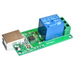
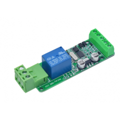
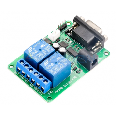
The other month, both for personal and professional interest, I began to explore the world of automating electrical devices connected to mains supply. That is, switching on and off electrical loads with relays. In order to start with something simple, I found an ultra cheap two relay board on ebay, compatible with both PCs, Arduinos and Raspberry PIs. It's probably the cheapest device of its kind available - I got it for 2.75 EUR shipped from China to Italy in about three weeks (!). It's called a ICSE013A board from http://www.icstation.com/
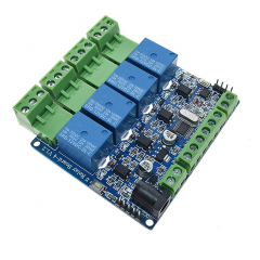
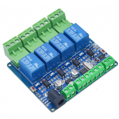
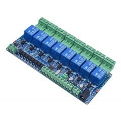
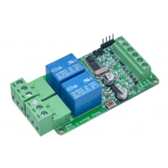
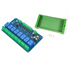
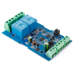
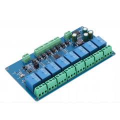
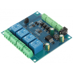
I don't know if the device is actually still produced, but it's part of a family of similar boards, along the ICSE012A (4 relays) and ICSE014A (8 relays). Here is the bare-bones board, it's shipped in bubble wrapped plastic bag with no instructions:
 Ver más grande
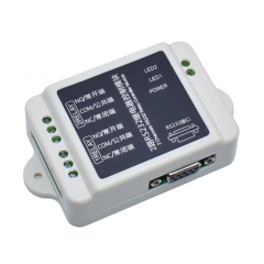
Icstation Icse013a Modulo Rele 2ch Comando Usb Itytarg
MLA665579187
Nuevo producto
4 artículos
Más
Controlling a ICStation relay board (ICSE013A ICSE012A ICSE014A) from .Net (and Arduino)
Software and documentation must be downloaded from the manufacturer's site. Try here - it's the 4 relay board, but it's the same. What you get is a test program for Windows and two pages of documentation. There is a chinese version and an almost incomprehensible 'chinenglish' translated version. The theory of operation is actually pretty simple, even if to verify it I resorted to monitoring the serial traffic from/to the test program with a serial software monitor. To control this board, and the others, one must operate as following :
- Set the serial parameters to 9600 bit/s, 8 bit data, no parity, 1 stop bit
- The board expects single byte commands and outputs single byte id packets.
- When plugged in/switched on the board expecs an hex 50 command. When sent this command before operations the board will respond with a single byte id code. For the ICSE013A 2 relay board its hex AD. AB for the 4 relay model and AC for the 8 relay model
- After this one must send an hex 51 command to start switching relays on and off. After this command, sending a request id hex 50 will no more result in the board sending back its id until it's switched off and then on.
- So to initialize the board first send hex 50, handle the id code if needed, then send hex 51.
- To switch relays on and off and on one must always compute a single byte command representing the status of the individual relays. The first relay is represented by the lowest order bit in the command byte, the second in the second lowest order bit, and so on for the other relays of the other boards. Of course a 'switched on' relay with the NO contact closed it's represented by a 1 bit, the reverse by a 0 bit.
- For the 2 relay board, the command to set both relays off it's 0, binary 00000000. To switch the second relay on, it's decimal 2, binary 00000010. To switch on both relays, it's dec 3, binary 00000011, to switch on the first relay, dec 1, binary 00000001.
- It must be noted that the command always switches on AND OFF relays according to its data. For example if both relays are on and I send a 00000001 command only the first relay will be kept on, since the second-lowest order bit it's 0, that is, switch off relay 2!
- In other words, the board does not keep the state of its relays in its protocol, this is always the programmer's responsibility. There are NO commands to retrieve the relays status.
- It's also important to set a starting state for the relays beginning operations, since the hex 51/50 commands act strangely in this respect (a 51 command seem to switch a relay off when issued for the second time, e.g.)
- Bits for relay not physically present on the board, for example trying to set the 8th relay on the 2 relay board, are simply ignored.
Esta placa utiliza driver USB PROLIFIC,
Link
http://www.prolific.com.tw/US/ShowProduct.aspx?p_id=225&pcid=41
20 productos más en la misma categoría:
-
Rele 5v Comando Usb Por Pc...
-
Modbus Rs485 12v 4ch Inp Opto +...
-
Modbus Rs485 5v 4ch Inp Opto +...
-
Modbus Rs485 Modulo 12v 8ch Inp...
-
Modbus Rs485 Modulo 12v 1ch Inp...
-

Modbus Rs485 Modulo 5v 1ch Inp...
-

Modbus Rs485 Modulo 12v 2ch Inp...
-
Modbus Rs485 Modulo 5v 2ch Inp...
-

Modbus Rs485 Modulo 5v 8ch Inp...
-
Modbus Rs485 Modulo 7-24v 8ch...
-
Modbus Rs485 Modulo 5v 2ch Inp...
-
Modbus Rs485 Modulo 7-24v 8ch...
-
Modbus Rs485 Modulo 5v 4ch Inp...
-
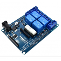
Shield Rele 4ch 70w Arduino Uno...
-
Actuador 4ch Comandos Rs232 Rele...
-
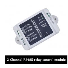
Rs485 2ch Modulo 9-30vdc 2 Rele...
-
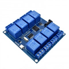
Icstation Icse014a Modulo Rele...
-
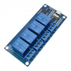
Icstation Icse012a Modulo Rele...
-
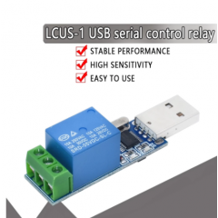
Rele Domotico Inteligente Lcus-1...
-
Modulo De Control 2ch Rele...
-

Mejor Precio Garantizado
En nuestra tienda encontrará los mejores precios.
-

Soporte
Por cualquier duda, puede comunicarse con nosotros.
-

Ofertas
Acceda a las mejores ofertas en nuestros productos.